Raypak Electronic Combination Gas Valve | Natural Gas - IID Units | 003900F
$291.22
|
|
|
|
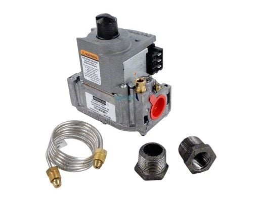
Combination Gas Valve Natural Gas Electronic IID
This .5in gas valve fits models:
- 53, 53A, 53B, 055B
- 151, 153, 153A
- Gemini 181-401
- Versa 183-403, 183A-403A 183B-405B
- RP21000 185-405
- P-R 185A-405A, C-R 185A-405A
This kit includes:
- Gas Valve
- (2) 1/2" x 3/4" reducing bushings
- Valve support bracket
- (2) screw hex head #10 x 3/8
- 1/8"O.D. X 3" pilot tubing
- Installation instructions
SCOPE:
This installation kit is to be used on heater models equipped with standing pilot Millivolt or electronic ignition systems. Refer to the model numbers shown above.
INSTRUCTIONS:
- Turn off electricity to heater.
- Turn off gas to heater.
- Allow heater to cool down before installing this kit.
Instructions for models 53, 53A 53B, 055A and 055B to remove old gas valve:
- Remove lower front door
- disconnect gas line from gas valve
- Remove (2) screws holding burner tray to unit, and (2) screws that secure gas valve bracket to rear of jacket (Models53, 53A & 53B)
- Disconnect wires that terminate at gas valve.
- Slide out burner tray
- Disconnect and remove pilot tubing and bleed line (if used) from gas valve and pilot burner.
- Turn gas pipe (manifold) to vertical position and unscrew the gas valve (Models 53 and 53A only)
- Disconnect U-bolt, remove gas valve with manifold from burner tray, then remove manifold from gas valve (MOdel 53B and 55A)
Instructions for models 53, 53A, 53B, 055A and 055B to install replacement gas valve
- Install brushings in inlet and outlet openings of gas valve
- Caution: Do not use excessive pip dope in pipe connections. Leave end two threads uncoated. Pipe dope must be resistant to natural gas and propane gas.
- Check gas flow arrow or inlet markings on gas vavle and install pipe manifold in outlet of gas valve.
- Install new 1/8" pilot tubing to pilot burner.
- Note: Avoid sharp bends or kinks in pilot tubing.
- reverse procedures in removal of old gas valve.
Instructions to remove old gas valve models: 151, 153, 153A, 155A, Gemini 181-401, Versa 183-403, 183A-403A 183B-405B RP2100 185-405, P-R 185A-405A, C-R 185A-405A
- Install brushings in inlet and outlet openings of gas valve.
- Caution: Do not use excessive pipe dope on threaded pipe connections. Leave end two threads uncoated. Pipe dope must be resistant to fuel gas being used. (Natural and Propane)
- Check gas flow arrow on inlet markings of gas valve and install pipe manifold in outlet of gas valve.
- Attach and secure valve support bracket.
- Install new 1/8" pilot tubing to pilot burner and gas valve.
- Note: Avoid sharp bends or kinks in tubing.
- Reverse procedures in removal of old gas valve.
Brand: Raypak
Raypak Electronic Combination Gas Valve | Natural Gas - IID Units | 003900F
$291.22
Platinum Preferred Manufacturer
This part fits the following products


Product description
Features and details
Warranty

HABLAMOS ESPAÑOL
OPEN 6 DAYS A WEEK
Phone Support (Central Time)
6am - 6pm Monday - Saturday
6am - 6pm Monday - Saturday
NEWSLETTER
COMPANY
ABOUT US
CONTACT US
CONTACTO
CUSTOMER REVIEWS
FAQ
HOURS OF OPERATION
PRIVACY
SITE MAP
TESTIMONIALS
ABOUT US
CONTACT US
CONTACTO
CUSTOMER REVIEWS
FAQ
HOURS OF OPERATION
PRIVACY
SITE MAP
TESTIMONIALS
MY ACCOUNT
RETURN MERCHANDISE
PROMOTIONS
COUPONS
SALES
REBATES
NEWSLETTER
BREAD FINANCING
PROTECTION PLANS
RETURN MERCHANDISE
PROMOTIONS
COUPONS
SALES
REBATES
NEWSLETTER
BREAD FINANCING
PROTECTION PLANS
TERMS
INTERNATIONAL ORDERS
LOYALTY POINTS TERMS
RETURNS POLICY
SHIPPING POLICY
RESOURCES
BLOG
PRODUCT MANUALS
INTERNATIONAL ORDERS
LOYALTY POINTS TERMS
RETURNS POLICY
SHIPPING POLICY
RESOURCES
BLOG
PRODUCT MANUALS

v1.0.3p